 |
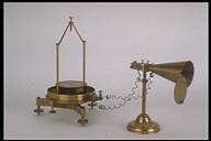
Melloni's thermo-multiplier |
 |
Termomoltiplicatore del Melloni |
| Subject: thermoelectricity, radiant heat gauge |
Settore: calore/misuratore dell'intensità della radiazione termica |
| Numbers of catalogue: 1 - 37 |
Numeri di Inventario: 1, 37 |
| Engraved on the brass box enclosing the thermo-electric elements of the pile: "F. De Palma"; engraved on the graduated silver-plated brass ring of the galvanometer: "F. De Palma" |
Sulla scatola d'ottone che racchiude gli elementi termoelettrici: "F. de Palma" [inciso]; Sull'anello graduato d'ottone argentato del quadrante: "F. de Palma" [inciso] |
| 1871 [document] |
Periodo di costruzione: 1871 [documento] |
| Brass, bone, antimony, bismuth, ebonite, copper, silk |
Materiali utilizzati: Ottone, osso, antimonio, bismuto, ebanite, rame, seta |
Thermopile: conic collector Ø max 65 mm; height: 215 mm |
Dimensioni: Pila: collettore conico Ø max. 65 mm; altezza: 215 mm |
| Galvanometer: 205 X 205 X 295 [mm] |
Dimensioni: Galvanometro: 205 X 205 X 295 [mm] |
| |
|
This device allows for the detection of weak sources of infra-red radiation using the thermo-electric effect.The Danish physicist Oersted and the French physicist Fourier invented the first thermo-electric pile in circa 1823 by working with pairs of small antimony and bismuth bars welded in series. In 1829 Nobili designed a new instrument for the measurement of thermic radiations, a sort of "electric thermometre" that, following improvements by Melloni, accounted for a crucial technological innovation that allowed for a correct theoretical interpretation of thermic radiation. The new device consisted of a thermopile connected in series to the clips of the astatic galvanometer, which was also created by Nobili. He called it thermomultiplier or electric thermoscope. For most of the 19th century the thermomultiplier proved to be an irreplaceable instrument in the study of thermic radiation for its high reactivity and quickness. This instrument is signed by the Neapolitan mechanician Filippo De Palma. |
Questo dispositivo, sfruttando l'effetto termoelettrico, permette di rilevare deboli sorgenti di radiazione infrarossa. Furono il fisico danese Oersted ed il francese Fourier, intorno al 1823, a mettere a punto la prima pila termoelettrica, lavorando con coppie saldate in serie di sbarrette d'antimonio e di bismuto. Nel 1829, Nobili ideò un nuovo strumento di misura per la radiazione termica, una specie di "termometro elettrico" che, in seguito ai successivi perfezionamenti apportati dal Melloni, costituì una innovazione tecnologica decisiva verso la corretta interpretazione teorica della radiazione termica. Il nuovo strumento si componeva di una termopila collegata in serie ai morsetti del galvanometro astatico, anch'esso ideato dal Nobili. A tale strumento egli diede il nome di termomoltiplicatore o termoscopio elettrico. Per gran parte del XIX secolo, il termomoltiplicatore, in seguito alla grande sensibilità e prontezza raggiunta, si rilevò uno strumento insostituibile nello studio della radiazione termica. Il presente strumento è firmato dal meccanico napoletano Filippo de Palma. |
| |
|
Description of the thermopile: A brass base and a brass stem, the height of which could be adjusted through a ring screw locking nut, support the pile, which is inside a brass box with two binding posts at each side, which are fitted into two insulating bone sheets; at the top of it there are locking screw nuts that allow for the fixing (both in the front and in the back) of the brass thermic radiation collectors. The thermopile is made up of 30 pairs of thin sheets of different metal, most likely constantan copper. They are parallel and connected in series through weldings at their ends, so that all the even (upper) order weldings are on one extremity and all the uneven (lower) order weldings are on the other extremity. The series of sheets, which are dipped into an insulating putty, form a small parallelepiped enclosed in a brass case. The two plain faces are uncovered and they are respectively obtained by the alignment of the even ordered and of the uneven ordered weldings. The ends of the weldings are linked to the terminal posts. A truncated cone brass collector with a door, which is also a good screen against possible secondary external sources, conveys the "radiant heat" to the even ordered surface. The other surface is enclosed in a second (smaller) box-shaped collector with a door. For the description of the galvanometer see inventory number 175 (Fig. 67). |
Descrizione della pila: una base ed un gambo d'ottone, quest'ultimo regolabile in altezza tramite una vite di bloccaggio ad anello, sostengono la pila, racchiusa in una scatola anch'essa in ottone, munita ai lati di due serrafili montati su due lastrine d'osso isolanti e superiormente di due viti di bloccaggio per poter fissare anteriormente e posteriormente i collettori d'ottone della radiazione termica. La termopila è costituita da 30 coppie di lastrine di diverso metallo, probabilmente rame-constantana, raccolte parallelamente e collegate in serie, tramite saldature ai loro estremi in modo tale che tutte le saldature di ordine pari (superiori) si trovino ad un'estremità e tutte quelle di ordine dispari (inferiori) all'altra. Il fascio di lastrine, immerso in un mastice isolante, forma un piccolo parallelepipedo incassato in un astuccio d'ottone con le due facce piane scoperte, ricavate rispettivamente dall'allineamento delle saldature di ordine pari e da quelle di ordine dispari. Gli estremi della successione delle saldature sono collegati ai serrafili. Un collettore tronco-conico d'ottone con sportello, che funge anche da efficace schermo di eventuali sorgenti secondarie esterne, provvede a convogliare il "calore radiante" sulla superficie di ordine pari. L'altra superficie libera è racchiusa da un secondo collettore a scatola (più piccolo) con sportello. Per la descrizione del galvanometro si veda la scheda relativa al numero d'inventario 175 (figura 67). |
| |
|
Function: The truncated-cone collector is placed in front of the heat source to be measured and the rheofores of the astatic galvanometer are connected to the terminal posts of the thermomultiplier. If the heat radiation of the source is of low intensity one can find an approximate direct proportionality between the degrees of the angular deflection of the galvanometer's needle and the difference in temperature between the opposite weldings of the pile. If the heat radiation is more intense the proportion is more complex. In the second half of the 19th century the makers often provided each multiplier with a table, on which the intensity was expressed in degrees, indicating the existing relation between needle deflection and the constant intensity of thermic radiation. |
Funzionamento: si pone il collettore tronco-conico di fronte alla sorgente termica da sottoporre a misura e si collegano i serrafili del galvanometro astatico con quelli del termomoltiplicatore. Se l'irraggiamento termico della sorgente è a bassa intensità, si verifica con buona approssimazione una proporzionalità diretta tra i gradi di deviazione angolare dell'ago del galvanometro e la differenza di temperatura che si origina tra le saldature opposte della pila. Per irraggiamenti termici più consistenti, la relazione diventa più complicata. Nella seconda metà dell'ottocento, spesso, i costruttori fornivano per ogni termomoltiplicatore, una tabella, tabulata in gradi-intensità, della relazione esistente tra la deviazione dell'ago e l'intensità costante dell'irraggiamento termico. |
| |
|
Bibliography: Marco [1883], vol. II, p. 157; Carazza [1983], pp. 141-155; Ragozzino, Rinzivillo, Schettino [1989], pp. 139-166.
|
Bibliografia: Marco [1883], Vol. II, p. 157; Carazza [1983], pp. 141-155; Ragozzino, Rinzivillo, Schettino [1989], pp. 139-166.
|
|
|