 |
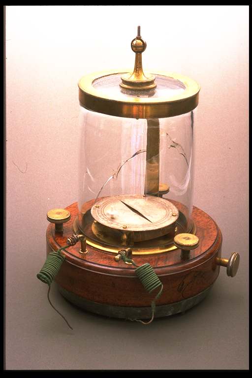
Nobili's portable galvanometer |
 |
Galvanometro portatile del Nobili |
| Subject: electrodynamics/electrical current gauge |
Settore: elettromagnetismo/ misuratore dell'intensità della corrente elettrica |
| Number of catalogue: 248 |
Numero di inventario: 248 |
| Unsigned, probably made by Corrado Wolf |
Non firmato, prob. Corrado Wolf |
| 2/4 of the 19th century |
Periodo di costruzione: 2/4 del XIX secolo |
| Mahogany, brass, silver, lead, ivory, silk |
Materiali utilizzati: Mogano, ottone, argento, piombo, avorio, seta |
Base: Ø max 135 mm; height: 205 mm |
Dimensioni: Base: Ø max. 135 mm; altezza: 205 mm |
| |
|
The design of the galvanometer is identical to the one created by the Physicist Leopoldo Nobili (1784-1835) in 1828. It is the same model as the great astatic galvanometer that was presented by the scientist from Reggio at the Italian Society of Sciences in 1826. This is, however, the "portable" model which is smaller, simplified and, therefore, easily handled and transported. With these models Nobili improved the precision of the galvanometer considerably and he definitely favoured the development of delicate scientific research particularly in the field of electrophysiology and thermoelectricity. This galvanometer was used to measure hydroelectric currents [1]. |
Il "design" del galvanometro è identico a quello ideato dal fisico Leopoldo Nobili (1784-1835) nel 1828. E' la versione "da viaggio" ridotta, semplificata e quindi facilmente trasportabile, del grande galvanometro astatico presentato dallo scienziato reggiano alla Società Italiana delle Scienze nel 1826. Con tali modelli Nobili incrementò notevolmente la sensibilità del galvanometro, favorendo in maniera decisiva lo sviluppo di delicate ricerche scientifiche, in particolare nel campo della elettrofisiologia e della termoelettricità. Questo galvanometro veniva usato per la misura di correnti idroelettriche [1]. |
| |
|
Description: The circular mahogany base of the galvanometer is provided in its lower part and in its inner part with a lead ring that increases the stability of the instrument. Brass foot screws at the base of the device allow for appropriate levelling. Two small brass gudgeon-pins can be inserted into two holes at the base and two copper wire coils insulated by green silk are still wrapped around them. The gudgeon-pins act as binding posts. In the centre of the base there is a rectangular brass frame around which a coil of copper wire is wrapped. The coil is insulated by thin yellow ochre silk. In the upper part of the coil is a rhomb-shaped opening allowing for the insertion of the lower needle of the astatic system. Above the coil, horizontally, there is the silver-plated quadrant of the galvanometer with a similar rhomb-shaped opening and a graduated scale engraved upon two concentric circular rings and divided into four quadrants that are graduated from 0° to 90°. The inner ring has thin marks for the division into degrees; the outer ring is graduated by a mark every 5 degrees. The points of the rhomboidal opening indicate the zero value on the scale, and they are placed parallel to the wires of the coil. Near one of the 90° markings, the quadrant is covered by an ivory peg with a lower tooth that prevents the lower needle of the astatic system from oscillating beyond a certain limit and the thread from entangling. A brass knob on the side of the base permits of setting the coil and the quadrant making them rotate in relation to the mobile equipment without moving the whole instrument. This can be carried out by means of an inner rack and pinion mechanism. A glass cylindrical bell, which is blocked by brass frames at its base, protects the instrument from external disturbances. The suspension mechanism of the mobile equipment can be vertically adjusted by rotating a small brass sphere linked to the external top of the bell. This instrument lacks the astatic system. |
Descrizione: La base circolare in mogano del galvanometro è inferiormente ed internamente zavorrata da un anello di piombo per aumentare la stabilità dello strumento. Tre viti calanti d'ottone attraversano la base e permettono di ben livellare l'apparecchio. Due piccoli spinotti d'ottone inseribili lungo due fori della base ed aventi ancora attorcigliate due spire di fili di rame ben isolati da seta verde, fungono da serrafili. Centralmente alla base è alloggiato un telaio d'ottone rettangolare, intorno al quale è avvolta una bobina di filo di rame ben isolata da seta finissima color giallo ocra. La bobina ha nel suo piano superiore una fessura romboidale per il passaggio dell'ago inferiore del sistema astatico. Sopra la bobina è posizionato orizzontalmente il quadrante argentato del galvanometro con la medesima fessura romboidale e la scala graduata, incisa su due corone circolari concentriche divise in quattro quadranti graduati da 0º a 90º. La corona interna ha una tacchettatura fine per la divisione in singoli gradi; l'esterna è graduata mediante tacche di 5º in 5º. Le punte della fessura romboidale indicano gli zeri della scala e sono orientate parallelamente ai fili della bobina. Il quadrante è attraversato, in vicinanza di una delle divisioni segnate 90º, da un piolo d'avorio con un dente inferiore che impedisce all'ago inferiore del sistema astatico di oscillare oltre un certo limite e al filo di attorcigliarsi più volte. Una manopola d'ottone che esce lateralmente alla base è in grado di far ruotare ed orientare, mediante un meccanismo interno a pignone e cremagliera, la bobina ed il quadrante rispetto all'equipaggio mobile, senza dover muovere l'intero strumento. Una campana cilindrica di vetro, bloccata alle basi da cornici d'ottone, difende lo strumento da eventuali turbolenze esterne. Il meccanismo di sospensione dell'equipaggio mobile può essere regolato in altezza mediante la rotazione di una piccola pallottola d'ottone fissata sulla sommità esterna della campana. Questo esemplare è mancante del sistema astatico. |
| |
|
Function: By moving the brass knob, the scale can be adjusted so that the zero values correspond to the directions of the earth's magnetic field. When inserted in series connection to an electrical circuit, the device gives a direct proportion (for slight deviation of the needle: up to 25°) between the angle and the intensity of the current. |
Funzionamento: agendo sulla manopola d'ottone si orienta la scala in modo tale che gli zeri abbiano la direzione degli aghi magnetici. Inserendo lo strumento in serie in un circuito elettrico esso forniva approssimativamente per piccole deviazioni dell'ago (circa 25º) una proporzionalità diretta tra l'angolo e l'intensità di corrente. |
| |
|
Bibliography: Nobili [1834], vol. II, pp. 36-40, table VI, fig. 1. |
Bibliografia: Nobili [1834], Vol. II, pp. 36-40, Table VI, fig.1 |
| |
|
[1] After the discovery in 1821 of thermoelectricity by the German physicist Thomas Seebeck (1770-1831), the origin of electric current was attributed to only two causes: that which is generated by the difference in temperature between the weldings of two different metals (thermoelectric current) and that which is produced by electrochemical reactions, such as with Volta's pile (hydroelectric current).
|
[1] Dopo la scoperta, nel 1821, della termoelettricità ad opera del fisico romantico tedesco Thomas Seebeck (1770-1831), l'origine delle correnti elettriche venne ricondotta a due sole cause: quella generata da una differenza di temperatura esistente tra le saldature di due diversi metalli (correnti termoelettriche) e quella prodotta da azioni elettrochimiche come, ad esempio, la pila di Volta (correnti idroelettriche). |