 |
Peltier's atmospheric electrometer |
 |
Elettrometro atmosferico di Peltier |
| Subjects: meteorology/atmospheric electricity gauge |
Settore: meteorologia/misuratore dell'elettricità atmosferica |
| Inventory Number: 294 |
Numero di inventario: 294 |
| Unsigned |
Non firmato |
| 2/2 of the 19th century |
Periodo di costruzione: 2/2 del XIX secolo |
| Copper, walnut, brass, glass |
Materiali utilizzati: Rame, noce, ottone, vetro |
Base: Ø 180 mm; height: 340 mm |
Dimensioni: Base: Ø 180 mm; altezza: 340 mm |
| |
|
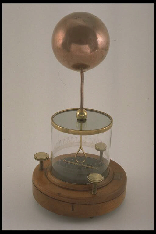
This electrometer with a horizontal index was designed in 1836 by the Parisian clockmaker and scientist Jean Charles Athanase Peltier (1785-1845): his primary objective was to measure the quantity of electricity in the air. Since 1752, when the electrical nature of lightning was proven by Franklin, the study of electric meteorology developed steadily until the end of the 19th century from both a theoretical as well as an experimental standpoint, due to increasing experimentation. This device is an important intermediate step in the making and improvement of those electrometers that, since the pioneering attempts by Nollet, Canton, Cavallo, De Saussure, De Luc, Bennet and Volta, had developed in the course of impassioned research on atmospheric electricity. This highly sensitive device, which was very popular in the second half of the 19th century, is based on the principle of electrostatic repulsion that was first introduced in 1784 with the famous torsion-balance by the French physicist Charles Auguste de Coulomb. Among the repulsion electrometers created before Peltier's model, is one made by the famous builder John Cuthbertson in Amsterdam (1789) as well as the one that was suggested by an english electricity expert, William Snow Harris (1834). |
Questo elettrometro a indice orizzontale fu ideato nel 1836 dall'orologiaio e scienziato parigino Jean Charles Athanase Peltier (1785-1845) con il primario scopo di misurare la quantità di elettricità presente nell'aria. La meteorologia elettrica, a partire dalla dimostrazione della natura elettrica del fulmine (1752) da parte del Franklin, fino alla fine del XIX secolo si sviluppò vieppiù in un crescendo di interessi e di studi, sia dal punto di vista teorico che sperimentale. Questo apparato rappresenta una importante tappa intermedia nella costruzione e nel perfezionamento di quegli elettrometri che, a partire dai pionieristici tentativi di Nollet, Canton, Cavallo, De Saussure, De Luc, Bennet e Volta, si svilupparono sull'onda delle appassionate investigazioni sulla elettricità atmosferica. Il dispositio, molto sensibile e popolare nella seconda metà del XIX secolo, si basa sul principio della repulsione elettrostatica inaugurato nel 1784 con la celebre bilancia di torsione dal fisico francese Charles Augustin de Coulomb. Tra gli elettrometri a repulsione, precedenti al modello di Peltier, si segnalano quello costruito dal rinomato costruttore di Amsterdam John Cuthbertson (1789) e il modello proposto da uno studioso di elettricità, l'inglese William Snow Harris (1834). |
| |
|
Description: The cylindrical glass box that encloses and protects the gauging system (with a horizontal needle) of the instrument from external agents is fixed on a special circular groove that holds the circular beech base with three brass levelling screws. A conductor passes vertically through a central hole on the upper base of the box; the conductor consists externally of a vertically placed rod that bears a light copper globe, and of a sort of brass ring that is fixed to a small horizontal brass rod, within the glass box. The small brass rod has two small spheres at its extremities, and it is fixed to a circular insulating base. The small brass rod and the ring are attached to a pointed pivot that passes through the ring. A very thin and light mobile copper index hangs above the point, and it is attached to a fragment of a magnetized needle so that the index has the weak tendency to come back towards the zero point of measure of the graduated scale. The scale is carved at the level of the index along the external surface of the glass cylinder: it has two zero readings and is divided into four quadrants, each of 90°. |
Descrizione: su una base circolare in faggio, dotata di tre viti di livello in ottone, è montata a pressione, su un'apposita scanalatura circolare, la scatola cilindrica di vetro che racchiude e difende da disturbi esterni il sistema misuratore (ad ago orizzontale) dello strumento. Sulla base superiore della scatola passa verticalmente, tramite un foro centrale, un conduttore costituito esternamente da un'asta sormontata da un leggero globo di rame e internamente da una specie d' anello d'ottone che si appoggia su una verghetta orizzontale, anch'essa d'ottone, impiantata sopra un sostegno isolante ed avente agli estremi due piccole sfere. La verghetta e l'anello sono infilzate da un perno terminante entro l'anello con una punta sulla quale è sospeso un sottilissimo e leggerissimo indice mobile di rame, solidale ad un frammento di ago calamitato, per dare al suddetto indice la debole tendenza a tornare verso lo zero della graduazione. Questa è incisa all'altezza dell'indice, lungo la superficie esterna del cilindro di vetro, con doppio zero divisa in quattro quadranti, ciascuno graduato da 0 a 90º. |
| |
|
Function: before the measurement, the small brass rod and the index are placed along the line of the scale which reads the two zeros, in the direction of the magnetic meridian. By subjecting the instrument to an electrified object, the index, in electrical contact with the fixed rod, moves to a certain degree as the result of electrostatic repulsion; the angle of deflection depends on the quantity of charge it has received [1] by induction from the atmospheric layers. The choice of adopting a sphere rather than a point in order to capture electricity in the air is explained by Peltier as follows: "with points the influence phenomenon is accompanied by another phenomenon that has always led to the misinterpretation of the real use of the former one [...], with points the electricity is not bound enough".
|
Funzionamento: prima di eseguire la misura, si posizionano la verghetta e l'indice lungo la linea del doppio zero della scala nella direzione del meridiano magnetico. Avvicinando lo strumento ad un corpo elettrizzato, l'indice, che è in contatto elettrico con la verghetta fissa, devia per repulsione elettrostatica di un angolo che è correlato con la quantità di carica ricevuta [1] per induzione dagli strati atmosferici. La scelta di adottare la sfera, anzichè la punta, per catturare l'elettricità nell'aria, è così spiegata dal Peltier: «con le punte al fenomeno d'influenza viene ad aggiungersene un altro, che ha sempre fatto travisare la vera causa del primo....., non restando con esse l'elettricità abbastanza imprigionata».
|
| |
|
Bibliography: Peltier [1836], pp. 422-432; Hackmann [1978], pp. 3-34; Palmieri [1883], pp. 772-778; Secchi [1861], pp. 265-270. |
Bibliografia: Peltier [1836], pp. 422-432; Hackmann [1978], pp. 3-34; Palmieri [1883], pp. 772-778; Secchi [1861], pp. 265-270 |
| |
|
[1] The relation between charge and angle is not very clear. Peltier used a torsion-balance to write tables in which he not only reported the natural degrees but also those equivalent in tension. Quetelet used instead the method that had already been experimented by Volta and by Saussure in order to graduate special kinds of pith-ball electrometers. |
[1] La correlazione carica-angolo, non è del tutto lineare. Peltier, avvalendosi di una bilancia di torsione, compilava delle tavole nelle quali, accanto ai gradi naturali, segnava i gradi equivalenti in tensione. Il Quetelet si avvalse invece del metodo già praticato dal Volta e dal Saussure per graduare gli elettrometri a pondolini |
|
|