 |
Electrostatic machine with self-excitation Töpler-Voss |
 |
Macchina elettrostatica con autoeccitazione Töpler-Voss |
| Subject: electrostatics/charge induction generator |
Settore: elettrostatica/generatore ad induzione di carica |
| Number of catalogue: 264 |
Numero di inventario: 264 |
| On the walnut base: "A. Dall'Eco, Firenze Viale Principe Eugenio 14-30" [engraved on a brass ovoidal plaque] |
Costruttore: sulla base "A. Dall'Eco, Firenze Viale Principe Eugenio 14-30" [etichetta ovoidale d'ottone] |
| 1882 [document] |
Periodo di costruzione: 1882 [inventario] |
| Walnut, glass, brass, ebonite, paper, tinfoil, cork |
Materiali utilizzati: Noce, vetro, ottone, ebanite, carta, stagnola, sughero |
355 X 495 X 370 [mm] |
Dimensioni: 355 X 495 X 370 [mm] |
| |
|
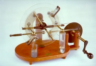
This model of an electrostatic induction generator, very much in vogue for electromedical purposes towards the end of the nineteenth century, is based on the principles of electrophorus and duplicator function. It is derived from the mechanical improvements made between 1865 and 1880 by the Russian physicist August Töpler, the German physicist Wilhelm Holtz (1836-1913) and by J. Robert Voss, a mechanician from Berlin. Voss devised this self-excitation model in 1880, perfecting a machine presented by Töpler the previous year. |
Questo modello di generatore elettrostatico ad induzione, molto in voga verso la fine del XIX secolo per scopi elettromedicali, si fonda sui principi di funzionamento dell'elettroforo e del duplicatore e deriva dai perfezionamenti meccanici apportati tra il 1865 e il 1880 dal fisico di origine russa August Töpler, dal fisico tedesco Wilhelm Holtz (1836-1913) e dal meccanico di Berlino J. Robert Voss. Quest'ultimo ideò nel 1880 questo modello ad autoeccitazione perfezionando una macchina presentata l'anno precedente da Töpler. |
| |
|
Description: The machine rests upon a footed walnut base. A column horizontally supports the axis of rotation. Two thin, shellacked, parallel glass disks in close proximity one to the other are vertically hinged to this axis. The larger of the two (the rear one), is a fixed disk and rests on the base along the groove of an ebonite insulation disk; the other (the front one), is a smaller mobile disk and rotates by means of a crank that controls a pair of pulleys connected by a cord. On its outer side, the fixed disk carries the inductors, two strips of tinfoil glued in the middle of two, broad paper shields placed diametrically, one beside the other. The mobile disk carries the Toepler-Voss self-excitation system consisting of six metallic buttons, each surrounded by a ring of tinfoil, placed equidistantly in a circle. Two small metal brushes rub against the buttons; the brushes are fixed to a curved conductor (covered with ebonite) that is clamped to the disks at opposite points and is in contact with the inductor's tinfoil strips. In front of the buttons, fixed to the edge of the mobile disk towards the horizontal diameter, two brass collection combs, each having 10 points, are positioned in the direction of the disk. The combs are in contact with the inner shields of two Leiden jars, (one of which is broken) and with the arms of the spark-gap, two brass bars equipped with spherules and insulation handles, into which the sparks are released. The outer shields of the Leiden jars rest on two brass disks electrically connected by a metallic wire (missing), which passes along the base. A second pair of collection combs, facing the mobile disk, each with eight points and a central metal brush that rubs against the buttons, comprises the so-called "diametrical conductor". The "diametrical conductor" is inclined at 45° with respect to the horizontal diameter and allowed for the polarity of the linings to be maintained unaltered, especially when the exciting dynamos moved farther away than their normal explosive distance. |
Descrizione: la macchina poggia su una base in noce con piedini. Una colonna sostiene orizzontalmente l'asse di rotazione sul quale sono imperniati verticalmente due sottili dischi di vetro, verniciati di gomma-lacca, assai vicini e paralleli tra loro: l'uno (il posteriore), più grande, fisso, poggia sulla base lungo la scanalatura di un disco isolante d'ebanite; l'altro (l'anteriore), più piccolo, mobile, ruota tramite una manovella che comanda una coppia di pulegge collegate da un cordoncino. Il disco fisso porta sulla sua faccia più esterna gli induttori, due strisce di stagnola incollate nel mezzo di due ampie armature di carta poste in direzioni diametrali l'una con l'altra. Il disco mobile porta il sistema di autoeccitazione Toepler-Voss costituito da sei bottoni metallici, ciascuno circondato da una corona di stagnola, disposti circolarmente a eguale distanza tra loro. Contro i bottoni vanno a sfregare due piccoli pennelli di fili metallici, fissati su un conduttore ricurvo (ricoperto di ebanite) che abbraccia in punti opposti i dischi ed è in comunicazione con le striscie di stagnola degli induttori. Di fronte ai bottoni, fissati alle estremità del disco mobile nella direzione del diametro orizzontale, sono posizionati, rivolti verso il disco, due pettini collettori d'ottone, muniti ciascuno di dieci punte. I pettini sono in comunicazione con le armature interne di due bottiglie di Leyda (di cui una rotta) e con i bracciuoli dello spinterometro, due aste d'ottone mobili munite di sferette e manici isolanti entro cui si fanno scoccare le scintille. Le armature esterne delle bottiglie di Leyda poggiano su due dischi d'ottone connessi elettricamente da un filo metallico (mancante), passante sotto la base. Una seconda coppia di pettini collettori affacciati al disco mobile, ciascuno dotato di otto punte e pennello centrale di fili metallici che va a sfregare contro i bottoni, costituisce il cosiddetto "conduttore diametrale". Esso è inclinato rispetto al diametro orizzontale di 45° e permetteva di mantenere inalterata la polarità delle armature soprattutto quando si allontanavano gli eccitatori oltre la normale distanza esplosiva. |
| |
|
Function: Not even a weak initial charge is needed to start the machine; the self-excitation system automatically starts by turning the mobile disk clock-wise (when viewed from the front of the machine) using the special crank. The quantity of charge captured thruogh induction by the combs is collected by the two mobile, brass collection rings, the terminal spherules of the spark-gap are each charged by the opposite sign with respect to the sign of the comb with which they are in contact. In this manner the machine is able to produce sparks, at times very long ones, especially if the poles of the spark-gap are in contact with the internal shields of the two Leiden jars. |
Funzionamento: per mettere in funzione la macchina non è necessario fornire ad una armatura una carica iniziale, anche debole; l'autoeccitazione si innesca automaticamente facendo ruotare in senso orario (per chi guarda frontalmente la macchina) il disco mobile mediante l'apposita manovella. La quantità di carica catturata per induzione dai pettini, viene raccolta dai due collettori mobili d'ottone, lo spinterometro, le cui sferette terminali si caricano ciascuna del segno contrario rispetto al segno del pettine con il quale sono in comunicazione. In questo modo la macchina è in grado di produrre scintille anche molto lunghe, specie se i poli dello spinterometro sono in comunicazione con le armature interne delle due bottiglie di leida. |
| |
|
Bibliography: Anonimo [1893], Anno XII, Num. 42, pp. 660-662; Battelli [1896], pp. 717-722; Murani [1906], Vol. II, pp. 296-29 |
Bibliografia: Anonimo [1893], Anno XII, Num. 42, pp. 660-662; Battelli [1896], pp. 717-722; Murani [1906], Vol. II, pp. 296-297 |
|
|