 |
Astatic galvanometer |
 |
Galvanometro astatico |
| Subject: electrodynamics/electrical current gauge |
Settore: elettromagnetismo/misuratore dell'intensità della corrente elettrica |
| Numbers of catalogue: 175 |
Numero di inventario: 175 |
| Engraved on the graduated brass ring of the quadrant: "F. De Palma" |
Sull'anello graduato d'ottone del quadrante: "F. De Palma" [inciso] |
| 1870 [document] |
Periodo di costruzione: 1870 [documento] |
| Brass, ebonite, copper, silk, silver |
Materiali utilizzati: Ottone, ebanite, rame, seta, argento |
205 X 205 X 295 [mm] |
Dimensioni:205 X 205 X 295 [mm] |
| |
|
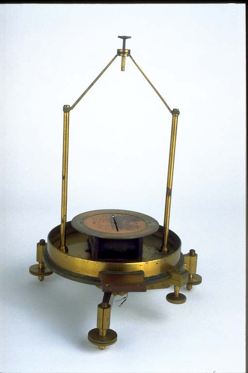
This is a Nobili galvanometer. This model was designed by the famous Parisian mechanician H. D. Ruhmkorff and became popular in the second half of the 19th century. From an account of expenditures we know this galvanometer was purchased from the Neapolitan mechanician Filippo De Palma (1813- c. 1870). |
E' un galvanometro del tipo Nobili, nella versione ideata dal celebre meccanico parigino Heinrich Daniel Ruhmkorff (1803-1877) che si impose nella seconda metà del XIX secolo. Da un rendiconto di spese, redatto dal Serpieri, sappiamo che esso fu acquistato presso il meccanico napoletano Filippo de Palma (1813-1875 circa).
|
| |
|
Description: Three brass levelling screws (which allow for the vertical placement of the instrument) support a robust circular brass base. On its external border there is a cylindrical glass bell (now lacking), which protects the instrument from draught. At the centre of the base a coil of copper wires is wrapped around an ebonite frame, the wires are insulated with a silk coating and their ends are linked to two brass rheofores (now lacking). The coil is placed under a horizontal copper disk, which is fitted into a silver-plated brass ring, upon which a semicircular scale with a central zero value is engraved. The zero value divides the two adjoining quadrants that are graduated from 0° to 90°. The copper disk also has the function of mitigating the needle oscillations by induction and it has a radial opening (at the level of the turns and of the 0° of the scale), in which the lower magnetic needle of the astatic system is introduced (now lacking). The astatic system reduces the action of the external magnetic field, and it is made up of two thin magnetic needles that have the same intensity, which are rigidly integral but have opposite polarities: one is above the graduated circle and functions as an index, and the other, which is placed in the coil, interacts with the magnetic field produced by the turns. The system hangs vertically above the centre of the disk by means of a cocoon thread the height of which can be adjusted through a screw on the top of the galvanometer. The base can be manually rotated so that the coil and the scale can be correctly placed in relation to the mobile equipment. A brass screw, which is external to the base, blocks the rotation of the base. |
Descrizione: tre viti di livello d'ottone (che permettono di disporre lo strumento in posizione verticale) sostengono una robusta base circolare, anch'essa d'ottone, sul cui orlo esterno è adagiata una campana cilindrica in vetro (mancante) che protegge lo strumento dalle correnti d'aria. Centralmente alla base, è avvolta su un telaio di ebanite una bobina di fili di rame, ben isolati tra loro da un rivestimento in seta, i cui estremi comunicano con due serrafili d'ottone (mancanti). La bobina è spazialmente collocata al di sotto di un disco orizzontale in rame, incastrato in una corona circolare d'ottone argentato, su cui è incisa una scala semicircolare, con zero centrale che divide due quadranti contigui graduati da 0º a 90º. Il disco di rame che ha anche la funzione di ammortizzare per induzione le oscillazioni degli aghi, presenta una fessura radiale (allineata alle spire e allo zero della scala) nella quale si introduce l'ago magnetico inferiore del sistema astatico (mancante). Questo ha il pregio di attenuare l'azione del campo magnetico esterno. E' costituito da un telaio di due sottili aghi magnetici paralleli, di eguale intensità, rigidamente solidali ma con polarità affacciate opposte: l'uno, posto al di sopra del circolo graduato, funge da indice, l'altro, alloggiato entro la bobina, interagisce con il campo magnetico prodotto dalle spire. Il sistema è sospeso verticalmente nel centro del disco di rame da un filo di bozzolo, regolabile in altezza tramite una vite posta sulla sommità del galvanometro. La base può essere ruotata manualmente in modo da permettere il posizionamento della bobina e della scala rispetto all'equipaggio mobile. Una vite d'ottone esterna alla base blocca a pressione la rotazione. |
| |
|
Function: The upper needle is placed in such as way that it is parallel to the thread of the coil (towards the magnetic meridian) and therefore on the zero of the scale. The instrument is inserted into a circuit in which current flows, thereby achieving the rotation of the needles produced by the action of the magnetic field created in the coil. This rotation is approximately proportional to the intensity of the current up to a maximum movement of about 25°. Beyond that limit it is necessary to list in special tables (through constant power sources or thermopiles) the values of intensity of the current according to the different angular deflections of the mobile equipment. |
Funzionamento: si posiziona l'ago superiore parallelamente ai fili della bobina (nella direzione del meridiano magnetico) e quindi sullo zero della scala. Inserendo lo strumento in serie in un circuito percorso da corrente, si ha la rotazione degli aghi prodotta dall'azione del campo magnetico creato nella bobina. Questa rotazione, fino ad una escursione di circa 25º gradi, risultava approssimativamente proporzionale all'intensità della corrente. Oltre tale limite, era necessario tabulare opportunamente (mediante sorgenti di corrente costanti o termopile) i valori dell'intensità di corrente erogati in funzione delle corrispondenti deviazioni angolari dell'equipaggio mobile. |
| |
|
Bibliography: Ganot [1855], pp. 634-637; Ferguson [1873], pp. 141-143; Palmieri [1833], pp. 267-270; Urbino University Library, envelope 17, file 6. |
Bibliografia: Ganot [1855], pp. 634-637; Ferguson [1873], pp. 141-143; Palmieri [1883], pp. 267-270, Archivio dell'Università di Urbino, busta 17, fascicolo 6.
|
|
|